During Covid I set about building a model railway.

Not your old school everyday model railway, but a fully computerised DCC N scale model-railway - just for the challenge of it.
It measures 3m x 1m, and is designed to fold up to my garage wall (once complete).
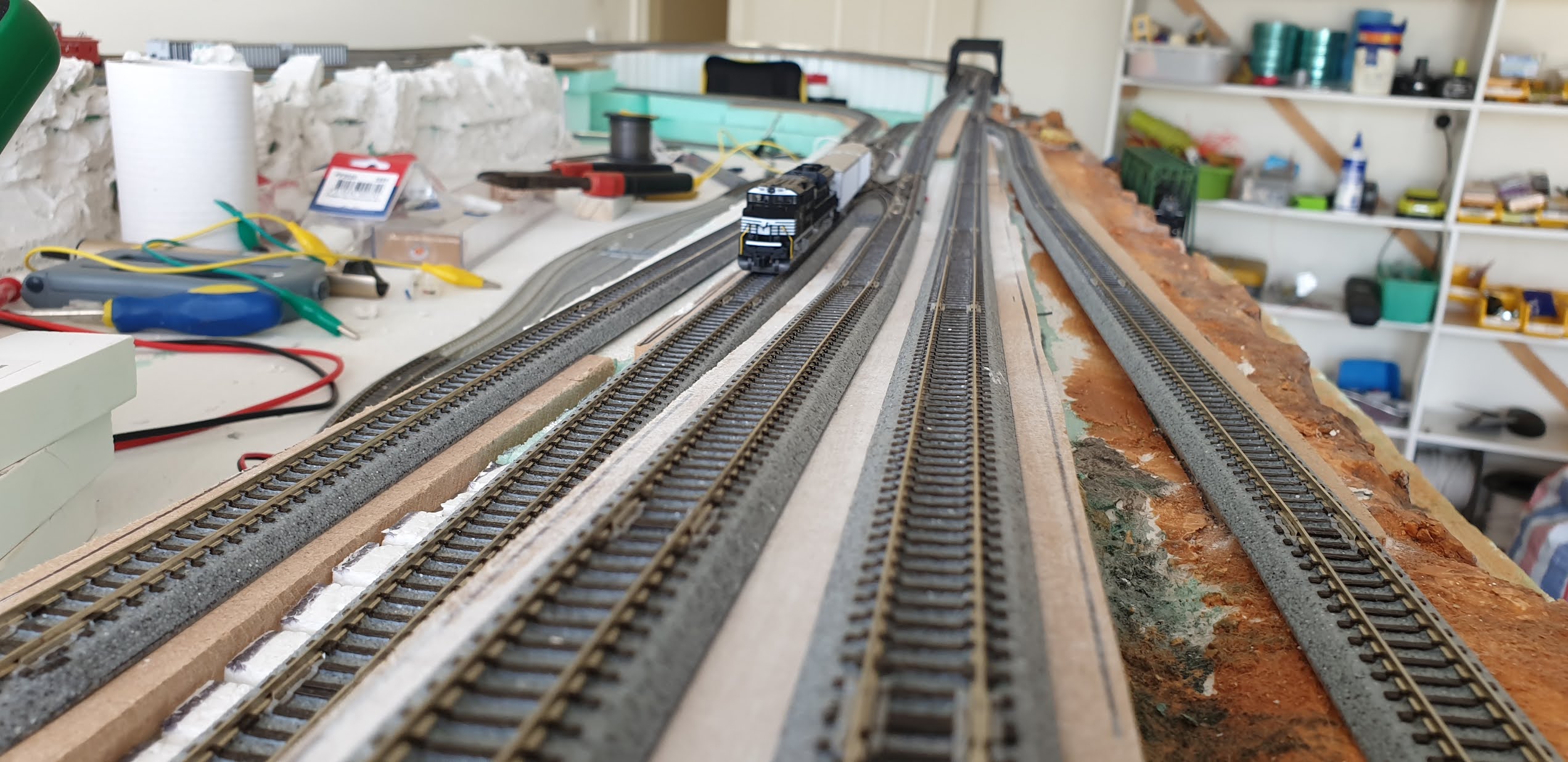
The layout looks as follows;


Why this layout ?
I used a computer to determine the best layout style to give multiple layers and many trains, but only using 8 switches. This layout allows for very long single run, reversing direction and multiple independent runs of both long and short trains. Limiting to 8 switches allows for some control without confusion.
This layout was very carefully considered to be allow complex usage while fitting in a smaller area.
My layout also features separate line (shown in Black), to allow the grand kids to play trains without fear of collisions :-)
My railway is an N Scale DCC++ Hybrid
What is DCC++ Hybrid
DC = Old school model railway, One train on the rail 12v supply.
DCC = Direct Command Control = A signal is sent through the rails to a decoder in each engine to control the engine speed, direction and many other functions. A purpose purchased or built command centre does the controlling.
DCC++ = As per DCC above, except that a computer can control the engines and switches via programming code.
DCC++ Hybrid = A combination of DCC and DCC++, using both a command centre and also a computer to control certain aspects of the layout - or even using the computer program to control the commend centre itself (which it what Im doing).
N Scale denotes that the Rail gauge is 9mm from rail to rail and all Engines and other items are scales accordingly.
About the Technology ?
There are a few elements to the Technology as simply explained below.
1) The Command Station (ESU 50310 7Amp) and Switch Controllers (DS74)

2) The Engine Decoders / and Switch Decoders
Small microcomputers installed in basic DC engines to allow them to decode computer signals and act accordingly. (eg speed, lights and sound etc). Rail Switches also have their own decoders and will switch when commanded also.
Here is a video where I show how to install these.
3) The Microcomputer Interface (home built)

It can also independent control separate sensors on the layout to make decisions etc.
I have used Arduino Mega 2560 R3's as my base microcontroller, in fact Im linking many of them together.
4) The Computer
The computer hoses the main logic code. I used "Process" language to control the Arduino, which in turn sends and read signals from the Command Station. In my case Im using an Apple Mac Laptop, but it is just the same on any Windows computer.

Cost?
Just dont even go there
How was it built ? - 25 Steps ! (more description will be added soon)


Photos and Video


No comments:
Post a Comment